
![]()
- New programs
- Code implementation and improvements in its application
- New display features common to several programs
- CYPECAD
- StruBIM Foundations
- CYPELUX, CYPELUX EN, CYPELUX CTE, CYPELUX RECS and CYPELUX LEED
- CYPELUX, CYPELUX EN, CYPELUX CTE and CYPELUX RECS
- CYPEFIRE Sprinklers
- CYPETHERM HE Plus, CYPETHERM RECS Plus and CYPETHERM EPlus
- CYPETHERM HVAC
- Arquimedes
- Return to the 2017 version download area
New programs
AcoubatBIM by CYPE
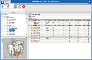
AcoubatBIM by CYPE is a tool developed by CYPE and the CSTB (Scientific and Technical Centre for Building) with the aim to help users study the insulation and acoustic conditioning of buildings. It calculates the indices that evaluate the insulation of airborne noise (indoor and outdoor), impact noise insulation and the reverberation level in indoor spaces, in accordance with the procedure contained in the EN ISO 12354:2017 code.
This application is integrated in the Open BIM workflows using the IFC standard.
The first version of AcoubatBIM by CYPE is included in the installation of CYPE programs in French and English. It will be implemented in more languages in upcoming versions.
More information on AcoubatBIM by CYPE in English.
More information on AcoubatBIM by CYPE in French.
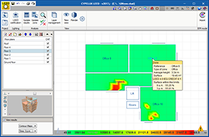
CYPELUX LEED
CYPELUX LEED is an application designed to help users comply with the Indoor Environment Quality requirements regarding natural light of the LEED certification (Leadership in Energy and Environmental Design). Specifically, the program verifies the LEED v4.0 CAI CREDIT 8.1 using option 2 (Simulation: Lighting calculations). In order to carry out this calculation, a BIM model that contains, at least, the geometric information of the building must be imported.
More information coming soon.
Code implementation and improvements in its application
Concrete structures
ABNT NBR 6118:2014 (Brazil)
Norma Brasileira ABNT NBR 6118 (2014). Projeto de estruturas de concreto – Procedimento.
Implemented in Embedded retaining walls and Reinforced concrete cantilever walls. This code was already implemented in CYPECAD, CYPE 3D and other CYPE programs.
Loads on structures. Seismic loads
General Method. Base shear and reorganisation of the panel
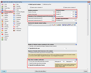
The “Base shear condition verification” has been implemented in the “Modal spectral analysis” of the “General seismic design method”. This check is optional and is implemented in the same way as, of previous versions, for the standards that contemplate this verification.
The section: “Estimation of the fundamental period of the structure” has been added, where users can indicate its approximate value in the “X” and “Y” directions. This data is used in the base shear verification.
The “Base shear condition verification” section has been added to the bottom panel, where users can select three options:
- Do not carry out the static base shear correction
- Specify the static base shear percentage
- Specify the modification factors
All the sections contain help buttons which provide information on the different options.
In general, the “Spectral modal analysis” data panel of the seismic analysis “General method” has been reorganised, the “Eccentricity factor” field has been added and the “Ductility” data can now be introduced for the “X” and “Y” directions.
New display features common to several programs
Start screen
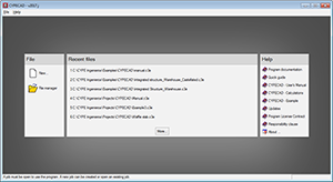
As of the 2017.j version when users access CYPE programs (except Arquimedes), they no longer access the last project that was open. Now a start screen is displayed where users can:
- Create a new project
- Find projects
- Select one of the latest projects that was accessed
- Select help documents of the program (Manual, New features, etc.)
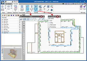
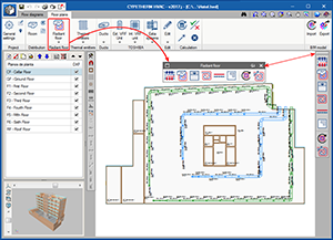
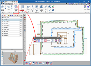
Floating tools
In the toolbar of some CYPE programs (e.g. in CYPETHERM HVAC and StruBIM Foundations), tools containing several options now display them in floating menus which can be placed anywhere on the screen.
These floating menus can be pinned to the screen by selecting the  icon located to the right of their heading (
  pinned not pinned), so that they do not disappear when another tool group is activated or when users access the program again.
Furthermore, the floating menus can have three different tool views which alternate upon pressing the  icon located to the left of their heading:
- Horizontal with large icons
- Vertical with large icons
- Vertical with small icons and descriptive texts of the tools.
The floating menus can be adhered to the sides of the work area to look like toolbars.
All these possibilities allow users to personalise the distribution of the tools to quickly access those which are used more often.
CYPECAD
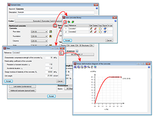
User concrete library
As of the 2017.j version, users can create different types of concrete with user-defined properties.
The concrete library can be accessed from the “General data” dialogue box (Project > General data). The different types of concrete of the library, as well as those established by the code, can be assigned to reinforced concrete elements.
StruBIM Foundations
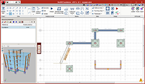
Beam analysis and design
As of the 2017.j version, StruBIM Foundations analyses and designs reinforced concrete and steel beams. Beams can connect footings, pile caps, mat foundations or pile supports.
Beam introduction
The beams are introduced on the floor plan by defining their initial and final points.
Analytical model
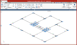
Once the beams have been introduced on the floor plans, the program carries out the analysis using the analytical model of the foundation plan. The beams are defined by bars bearing on the elements they connect. Once the analytical model has been generated, it may be edited to define loads, conditions etc.
The forces that are calculated for loadcases or combinations can be consulted from the “Beams” menu.
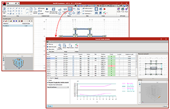
Beam design
Reinforced concrete beams are designed and checked in accordance with the ACI 318-14, ACI 318-11 and ACI 318-08 standards, and steel beams with the ANSI/AISC code. The design is carried out from the beam schedule, where users can:
- Define and edit reinforcement
- Consult forces
- Consult required reinforcement areas
- Consult the checks that have been carried out.
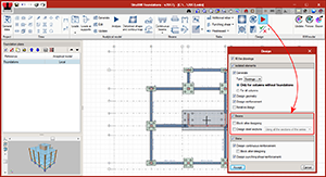
In the “Design” dialogue (which can be accessed by selecting the Design button), users can now select to design beams, as well as still having the options that were already present to design footings, pile caps and mat foundations.
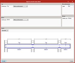
The beam reinforcement is designed in accordance with the typical concrete beam detail defined in General data. Continuous top and bottom reinforcement can be defined as well as additional reinforcement.
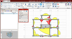
Interaction of beams with footings and pile caps
In previous versions of StruBIM Foundations, isolated elements (footings and pile caps) were designed and checked directly with the loads introduced on their associated support. As of the 2017.j version, users can choose between:
- Designing them only with the loads of the supports (forces of the “Global” model).
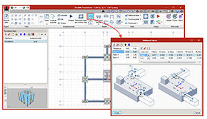
- Designing them with the loads of the supports and also considering the interaction with beams (forces of the “Local” model). The additional forces transmitted by the beams to the footings or pile caps can be consulted and edited from the “Additional forces” button.
In the analytical model, each footing or pile cap that is connected with beams is considered as a node with external fixity to which the beam will be connected. The loads at the supports and the additional forces transmitted by the beams will be taken into account in their design and check.
CYPELUX, CYPELUX EN, CYPELUX CTE, CYPELUX RECS and CYPELUX LEED
Layer management
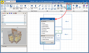
The “Layer management” option has been implemented in the “View” group of the toolbar of the program. This option displays a panel from which users can indicate which building elements are to be displayed on the floor plans of the project.
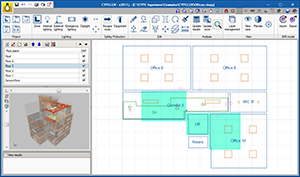
View of the floor slab above
As of the 2017.j version, CYPELUX displays the floor slabs from the floor above on the floor plan, as long as the project is linked to an architectural BIM model. This way, users can easily identify the presence of openings, which helps when introducing roof skylights.
The view of the floor above can be deactivated from the “Layer management” of the program.
CYPELUX, CYPELUX EN, CYPELUX CTE, CYPELUX RECS
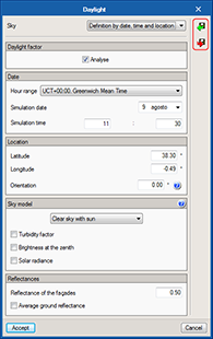
Daylight panel
As of the 2017.j version, the design configuration for natural daylight, defined in the Daylight option of the toolbar, can be saved to be used in future projects.
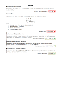
CYPEFIRE Sprinklers
New types of sprinklers
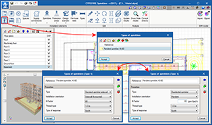
As of the 2017.j version the program includes the “type of response” of the sprinklers and two new types of sprinklers:
- Residential sprinklers
These are quick response sprinklers that are used specifically for dwellings, hotel rooms, hospital rooms, etc. - Standard sidewall sprinklers
These are like standard sprinklers (whose response can be standard or quick), but are used when there is a nearby wall. Their deflectors have a special design to discharge the water far from the wall.
It should be noted that the "Residential sprinkler" type of sprinkler does not have standard discharge K factor and that the checks of protected areas and maximum distances must be in accordance with manufacturer specifications. The program will check maximum values, which must not be exceeded in any case.
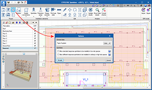
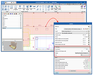
Design options
The “Project” tool group includes the “Options” button which opens a panel where users can indicate the use of different types of sprinklers which are only allowed under specific circumstances. The type of system used in the “Wet system” installation is also displayed.
More design options will be included in upcoming versions, such as: “Type of design (Hazen-Williams or Darcy-Weisbach)”, “Design accuracy”, “Specific weight of the fluid”, etc.
Consult sprinkler checks
The 2017.j version includes an individual report of the checks of the sprinklers. Now, it is possible to obtain a report with the checks that are carried out on each sprinkler and from which part of the code these checks are extracted.
This report can be obtained for Standard sprinklers, which already existed in previous program versions, and for the new types that have been introduced in this version: Residential sprinklers and Standard sidewall sprinklers.
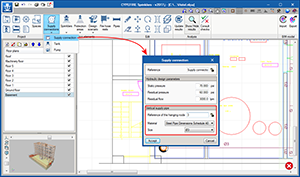
3D geometry
As of the 2017.j version, the following pipes can be used and edited in CYPEFIRE Sprinklers:
- The vertical supply pipe that connects the public network supply connection (or pressure set) to the sprinkler installation at each floor.
- The drop of the sprinklers with respect to their branch.
Work is currently being carried out on the 3D geometry of the program so that in upcoming versions, users can, for example, edit riser pipes, vertical pipes in the same floor, etc.
CYPETHERM HE Plus, CYPETHERM RECS Plus and CYPETHERM EPlus
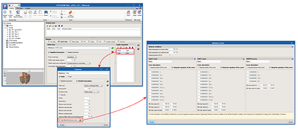
Edit behaviour curves of hot and cold water production equipment
The behaviour of the hot and chilled water production equipment varies depending on the working conditions. As of previous versions, the energy simulation programs of CYPETHERM that used the EnergyPlusTM analysis motor (CYPETHERM HE Plus, CYPETHERM RECS Plus and CYPETHERM EPlus), consider this variation using typical behaviour curves for each type of system that is defined in the “template” objects of EnergyPlusTM.
As of the 2017.j CYPE program version, users can edit behaviour curves of hydronic production equipment (boilers and coolers). For the equipment, users can choose whether to use the default curves or use user-defined behaviour curves. The program offers two options to introduce this data: in a table or as a polynomial curve.
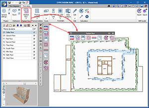
CYPETHERM HVAC
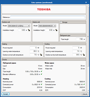
Aerothermal technology. Estia system from Toshiba
Aerothermal technology uses a heat pump system that produces hot water for heating and sanitary hot water, with the option to inverse the cycle for cold water.
The 2017.j version of CYPETHERM HVAC incorporates the Toshiba Estia aerothermal system. Estia is a split system that consists of an indoor unit and an outdoor unit, with a possible sanitary hot water accumulator. This system can be included in the flow diagram, or directly on the floor plan.
Due to outdoor conditions and the discharge temperature, the power offered by the equipment can be corrected in the panel. The program checks that the length of the pipe does not exceed the maximum permitted value; it reads the change in elevation between the indoor and outdoor units, and checks it does not surpass the maximum value that is allowed, and that the discharge temperature of the water lies within the working range of the machine.
On plan representation of Toshiba indoor units
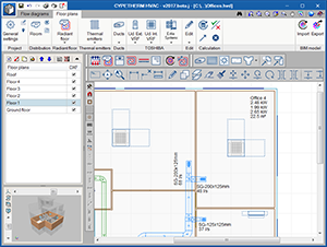
The on-plan display of Toshiba indoor units has been improved. Additionally, the required installation and maintenance space is now indicated using a dotted line.
Duct fittings
Two new ASHRAE discharge fittings have been added, for cross-shaped branches: a round duct with code SD5-24 and a rectangular duct with code SR5-21.
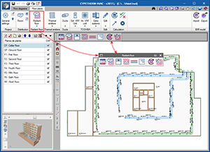
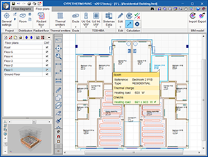
Design temperature of rooms and check
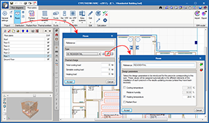
The design temperature for heating and cooling is defined for types of rooms. By unmarking the heating or cooling “check”, the heating or cooling load for that room will not be checked.
This case is represented in the “Residential Building ” example that is installed with the program. Aerothermal equipment with radiators and radiant floors to only cover heating loads, have been included in the building of this example. Therefore the cooling check is unmarked and no warnings will be displayed.
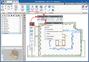
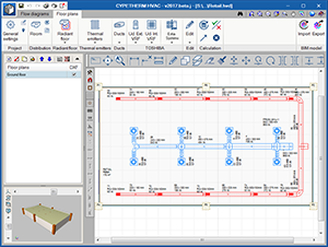
Dimensions and measuring tools
Three new tools have been included for measuring and dimensioning in the “Floor plans” tab:
- New dimension
- Delete dimension
- Measure lengths on plan
Arquimedes
Bill of quantities and measurements of Revit models
Quantities extraction of IFC files linked to a Revit project
As of the 2017.j version, the Bill of quantities of Revit models module of Arquimedes allows users to extract the quantities of IFC files linked to a Revit project. This way, users can obtain the global quantities of an Open BIM project composed of a Revit model and different IFC files associated with each discipline, such as the structure, lighting, electricity, air conditioning, fire safety, etc.
In previous versions, using the “Bill of quantities of Revit models” module, Arquimedes could only extract the quantities of Revit entities and could not extract those of IFC files linked to a Revit project.
Thanks to this improvement, when the quantities of a Revit model are to be extracted using the “Bill of quantities of Revit models” complement, regardless of whether users have opted to use the “Link with Arquimedes job” or “Generate quantities extraction file” option, an MCSV file will be created with the information of the main model and another for each IFC file linked to the project.
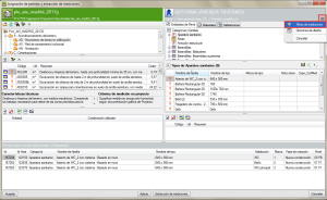
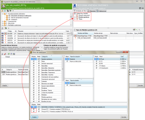
Once in Arquimedes, having linked the Revit project to a bill of quantities, whether it be directly or using the option in the “File > Connection with Revit > Import Revit quantities extraction file” menu, filters can be applied to manage the views and quantities of the information contained in the BIM project. This option is located in the “Assign job item and quantity extractions” window and is represented using the  button.
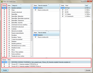
The Quantities filter dialogue box of this version allows users to mark the Categories which can be displayed in the “Assign job item and quantity extractions” dialogue box, using the selection boxes in the “Show” column. The “Measure” column allows users to mark the Categories, Phases and Levels which are to be measured upon pressing the “Quantity extraction” button. In the bottom part of the dialogue box, users can, similarly, activate or deactivate the view and quantities of the entities associated with each IFC file linked to the main model, and this way identify the information contained in each model and adjust their view and quantities.
This tool allows users to manage the quantities of all the entities and materials associated with a group of models associated to the group of models that make up a Revit Open BIM project from a single place.
Return to the 2017 version download area
Tel. USA (+1) 202 569 8902 // UK (+44) 20 3608 1448 // Spain (+34) 965 922 550 - Fax (+34) 965 124 950