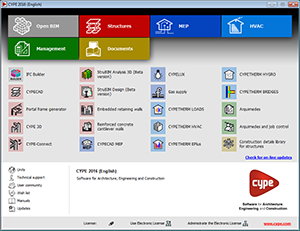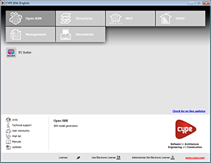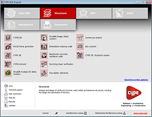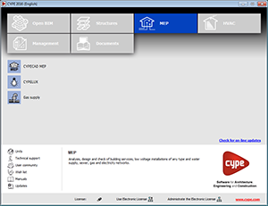
- Program menu. New arrangement
- New programs
- CYPECAD and CYPE 3D
- Open BIM technology as a project tool
- Open BIM workflow in specialised CYPE tools
- StruBIM Analysis 3D
- StruBIM Design
- CYPELUX and CYPELUX CTE
- CYPETHERM HE Plus, CYPETHERM LOADS, CYPETHERM Eplus
- CYPETHERM EPlus
- CYPETHERM HVAC
- CYPETHERM RT2012 and CYPECAD MEP (Thermique RT2012-France)
- Return to the 2016 version download area
Program menu. New arrangement
As of the 2016.e version, the CYPETHERM Suite program groups have been implemented (for their installation in English, Italian and French) as well as StruBIM suite (for its installation in English), which include, for each country (or influence area of each language) common and specific programs. For example, CYPETHERM Suite includes programs which are common to its installation in English, French and Italian such as the thermal loads and equipment program (CYPETHERM LOADS and CYPETHERM HVAC); and specific energy certification programs for countries (CYPETHERM RT2012 -France- and CYPETHERM C.E. – Italy).
The new program features were already covered by CYPECAD MEP, CYPECAD and CYPE 3D, but now the new applications have been designed in such a way that its use can be integrated in an Open BIM workflow.
The new applications are being developed so they contain the same features as their predecessors and will continue to function with them. Even though it seems that there is a tendency in the not so distant future to use related applications using Open BIM workflow, CYPE programs allow for work to be carried out using both philosophies.
Now, in the 2016.k version, the CYPETHERM and StruBIM suite programs are included in the Spanish, Galician, Spanish for Argentina and Spanish for Mexico versions. Due to this increase in program groups, the main CYPE program menu has had to be reorganised and redesigned; it now includes six program groups, with the possibility of the addition of new groups in future versions.
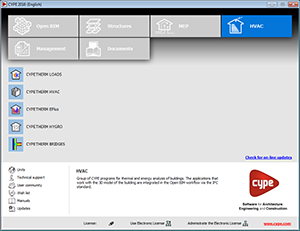
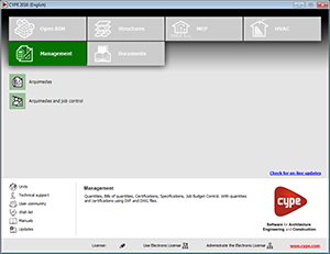
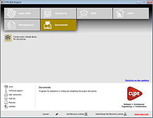
The images below show the current program groups (Open BIM, Structures, MEP, HVAC, Management and Documents) and the programs they contain (those that were present in previous versions and the new programs, prepared to operate in an Open BIM workflow).
New programs
MEP group
 CYPELEC NF (France)
CYPELEC version adapted to the French NF C 15-100 and NF C 14-100 codes.
The organisation of the CYPELEC NF modules is the same as that of the Spanish version (CYPELEC REBT). This implies that if users acquire any modules, they may be used for CYPELEC REBT and CYPELEC NF (the main permit for CYPELEC NF is different to that of CYPELEC REBT).
CYPECAD and CYPE 3D
Seismic code of Peru
The seismic code of Peru (Norma Técnica E.030 (2014) Diseño Sismorresistente) has been implemented in CYPECAD and CYPE 3D.
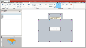
Advanced column editor
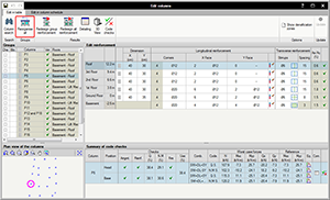
The 2016.k version of the advanced column editor includes a button to reorganise columns in alphanumerical order. This order is that generated by default after analysing the job.
Open BIM technology as a project tool
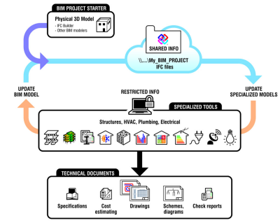
Using Open BIM technology a collaborative, multi-disciplinary and multi-user workflow can be implanted, which allows projects to be developed in an open, coordinated and simultaneous manner amongst the various project designers or agents that intervene in the project. In this workflow, proposed by CYPE, the project is solved in an iterative manner using the progressive solving of its various aspects or components.
This way of working is different to that proposed in the workflows based on BIM tools that previously existed in the market. Using these tools, the project is carried out based on the adopted solutions, in such a way that the work of the project designers who have to make project decisions based on loose and specific analysis models solved using specific applications.
The main property of Open BIM technology and, we believe, its main advantage is that it is based on open and public standard interchange formats (IFC), so that the contents of the BIM project are not linked to any specific application or program. Furthermore, thanks to the use of these interchange formats, the specific applications used to solve the various aspects of a project (structure, installations, etc.) do not have to be linked to a single software manufacturer.
The stages or actions contemplated in the workflow that is proposed to develop a project are:
- Beginning of the BIM project
- Use of specialised applications to solve the project
- BIM model update in specialised applications
- Export of IFC files to the BIM project
- Consolidation of the BIM model
Beginning of the BIM project
Based on an IFC file generated by IFC BUILDER or another modelling software (it does not necessarily have to be exclusively geometrical). To begin the BIM project, an empty directory has to be selected, since all the information that is deposited in the directory, as the project advances, will be interpreted as being part of the same BIM project.
Use of specialised applications to solve the project
All the applications can load the BIM model and work on it. Users must bear in mind that, some applications, can begin the development of the project without the need to have to be linked to a BIM model and create the link later on. For example, with CYPELEC REBT, users can begin the design of the electrical installation to then link it with a BIM model, later on when it is available, to introduce the floor plans on the model.
It is important to take into account that the analysis models of the various specialised applications are not loaded onto the shared or public BIM model. For example, in the case of CYPETHERM LOADS, the job or project of the program belongs to the designer that has performed the thermal load analysis, and no other project designer has access to the data file of CYPETHERM LOADS. This proposed workflow property is very important when assigning the responsibilities corresponding to all the technical staff that intervenes in the project.
BIM model update in specialised applications
Once the link with the BIM model has been created with the specialised applications, and with having begun the various projects, changes can be carried out on the model. The way in which CYPE applications react to the changes in the model to which they have been linked is one of the distinguishing and advanced properties of the Open BIM workflow.
In the proposed workflow, the specialised applications do not import a BIM model, since an import would imply that each time a change is carried out in the model, the work would have to be redone from the start. CYPE programs, which have been designed for this, UPDATE BIM models in such a way that if there are any changes in the original model, only work that has been carried out which remains obsolete after these changes is lost, and always with the user’s supervision, using the available update options.
Export of IFC files to the BIM project
As has been explained previously, the design models which manage the various specialised applications belong to the project designer that has created them and are not shared in the BIM project (they belong to the private field of each user). However, and this is a very important property of our applications, all of them can export an IFC file with information of each application. This way, the BIM project, after taking on this information, is progressively enriched and completed.
The information generated by the various applications can be, generally, of two types: it can be linked to entities that have been introduced previously in the BIM project (e.g. thermal loads generated by CYPETHERM LOADS which are linked to the precincts of the BIM project), or can consist of new project entities (e.g. the radiators or radiant floor circuits created in CYPETHERM HVAC).
Consolidation of the BIM model
Therefore, as the project is developed, the information corresponding to the BIM model increases using the IFC files generated by the specialised files. This is what we refer to as consolidation of the BIM model.
This, in reality, is very simple. The only thing to bear in mind is that the BIM model is not only the original IFC file, but it also consists of another file and of all the other files generated by the various specialised applications. This way, the BIM model which users work on includes all the consolidated information that has been generated amongst the specific applications that have been used.
This proposed workflow property allows for two very important, and very different, things to occur: on one hand the consolidations allows for interaction between the different specialised applications (e.g. CYPETHERM HVAC reads the thermal loads of the precincts that have been generated in CYPETHERM LOADS) and on the other, it unlinks the contents of the BIM project from the applications that have been used to develop it (the BIM project is not a file that belongs to a program, it is a collection of IFC files) and so this way the durability and accessibility of the developed work is guaranteed.
Open BIM workflow in specialised CYPE tools
StruBIM
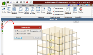
As of the 2016.k version the view of the BIM model and management of BIM links are incorporated in the program.
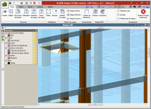
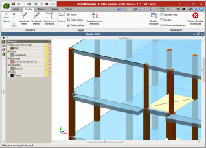
The view of the BIM model incorporates the representation of the linked IFC model or models in the view of the bar analysis model.
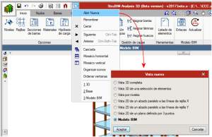
This view window is opened from the Window menu > Open new > BIM model.
The BIM model can be represented as transparent or solid, as well as having the option to view the analysis model.
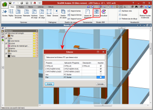
In the BIM model window, all the IFC models in the linked models list are displayed. Users can link the IFC files present in the directory containing the IFC files of the physical model with which the analysis model is imported (BIM project directory).
Changes in the IFC files of the BIM project directory are reflected in the Update button, which displays a warning notifying users that the model should be updated.

CYPETHERM
The specialised tools: CYPETHERM HE Plus, CYPETHERM LOADS, CYPETHERM HVAC and CYPETHERM EPlus, allow users to import geometric models in IFC4 format and export and import information related with the analysis and design of the building services of the building, which is obtained using the tools. This way the BIM model of the project is updated and the Open BIM workflow is closed.
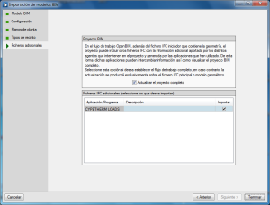
The four CYPETHERM tools allow users to automatically generate a new job by importing a BIM file with geometric information. Furthermore, each tool can import any additional IFC files generated by the remaining specialised CYPETHERM programs which may contain useful information for its design when the job is created or at any time during the design process of the job.
As the work is not carried out exclusively with one IFC file containing geometric information of the project, but with a group of IFC files containing the geometric, analysis and design information of the project, each BIM project must be generated in an individual directory to have all the information in a single place and for programs to only read the corresponding IFC files.
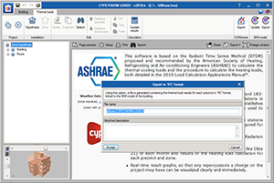
One of the many benefits of the Open BIM workflow can be seen, for example, in CYPETHERM LOADS and CYPETHERM HVAC. From CYPETHERM LOADS all the information of the thermal loads of the precincts can be exported to IFC format, once the project has been analysed. CYPETHERM HVAC requires the information of the thermal loads of the building to design the air conditioning systems. This information can be introduced by users or can be imported from the BIM project, if the data has been exported from CYPETHERM LOADS.
StruBIM Analysis 3D
View of the BIM model
As of the 2016.k version the view of the BIM model and management of BIM links are implemented in the program. More information on this new feature can be found in the “Open BIM workflow in StruBIM programs” section of this webpage.
StruBIM Design
Punching shear check
The 2016.k version of StruBIM Design includes a punching shear check for slabs in accordance with ACI 318-08, ACI 318-11 and ACI 318-14. The program automatically generates the critical section for each column that transmits forces to the slab. The program verifies, for the critical perimeter, if the tangential stress resistance is exceeded in slabs without shear reinforcement and exposed to bending in both directions.
Project data and structural element reports
Project data and structural element reports have been implemented in the 2016.k version of StruBIM Design. The report index is as follows:
- JOB DATA
- General data of the project
- Codes considered
- Actions considered and combinations
- Load patterns
- Loadcases
- Combination groups
- Limit states
- Materials used
- Concrete
- Reinforcement steel
- Covers
- General design properties
- COLUMNS
- Reinforcement
- Forces by loadcase
- Design properties (Concrete)
- Checks
- SLABS
- Reinforcement
- Required and provide reinforcement
- Checks
- BEAMS
- Reinforcement
- Forces by loadcase
- Required steel areas
- Checks
CYPELUX and CYPELUX CTE
Maintenance factor in accordance with CIE 97:2005
As of the 2016.k version, CYPELUX and CYPELUX CTE calculate the maintenance factor based on the method proposed by the CIE 97:2005 code (Guide on the maintenance of indoor electric lighting systems), for indoor precincts.
Export of lights to IFC files
As of the 2016.k version, CYPELUX and CYPELUX CTE allow users to export the geometric properties and technical data of the lights used in the lighting installation to a file with IFC format. This way, the BIM model us updated and the Open BIM workflow is closed.
CYPETHERM HE Plus, CYPETHERM LOADS, CYPETHERM Eplus
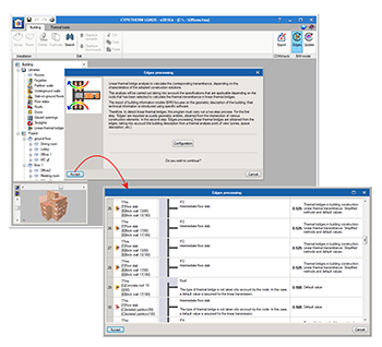
Generation of linear thermal bridges
CYPETHERM HE Plus, CYPETHERM LOADS and CYPETHERM EPlus analyse linear thermal bridges to calculate the corresponding transmittance values, depending on the properties of the adopted construction solutions.
This analysis is carried out taking into account the specifications to be applied depending on the code that has been selected to calculate the thermal transmittance in linear thermal bridges.
BIM models contain the geometric description of the building, whereas technical information has to be introduced using specific programs.
Therefore, to detect linear thermal bridges, the program must carry out a two-stage analysis. During the first stage, ‘Edges’ are imported as purely geometric entities, obtained from the intersection of two different construction elements. The second stage consists of the ‘Linear thermal bridge analysis’ which obtains the linear thermal bridges and their corresponding transmittance values based on the edges, and depending on the properties of the adopted construction solutions and the description of the building from the thermal analysis point of view (zone distribution, space description, etc.).
CYPETHERM EPlus
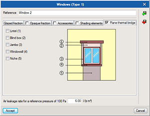
Plane thermal bridges
As of the 2016.k version, users can introduce plane thermal bridges at windows: lintel, blind box, jambs, windowsill and niche.
CYPETHERM HVAC
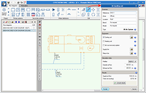
Analysis and design of Air Handling Units (AHU)
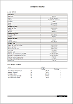
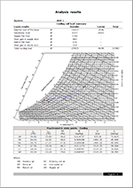
As of the 2016.k version, CYPETHERM HVAC allows users to carry out the analysis and design of air handling units by configuring their main elements (cooling and heating coils, discharge and return ventilator flows, heat recoverers) in accordance with the design requirements of the zone as well as the situation characteristics.
The program generates a results report containing:
- Indoor and outdoor design conditions
- Data sheet of the air handling unit
- Thermal load summary
- Graphical representation of the air cycle using the psychrometric chart.
Radiators
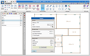
As of the 2016.k version, users can analyse and design radiators in CYPETERM HVAC, in its “Floor plans” tab. And so, users now have the option to use radiators and/or radiant floors as air conditioning systems designed by the program.
Distribution of the thermal load of the precincts amongst the systems
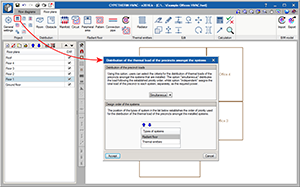
To design and/or check the power provided by the equipment in a precinct, the program offers users the option to distribute the thermal load amongst the installation elements that have been introduced in each precinct. In this sense, the program offers two criteria to carry out the distribution:
- Simultaneous
Distributes the load amongst the installed systems in accordance with their priority. - Independent
Separately assigns the total load of the precinct to each system, as the total required power.
If users select Simultaneous, they will establish the priority of the different systems to be used during the thermal load distribution of the precincts.
CYPETHERM RT2012 and CYPECAD MEP (Thermique RT2012-France)
BEPOS-Effinergie 2013
In the 2016.k version of CYPETHERM RT2012 and CYPECAD MEP (Thermique RT2012) users can verify, in the RT 2012 analysis, the requirements of BEPOS are met. This check is carried out in the Étude thermique réglementaire RT 2012 report.
Combustion generators
More combustion generators have been added. As of this version, users can introduce hot air generators (standard or condensation) or radiant generators (tubes and panels).
Return to the 2016 version download area
Tel. USA (+1) 202 569 8902 // UK (+44) 20 3608 1448 // Spain (+34) 965 922 550 - Fax (+34) 965 124 950
